-
Notifications
You must be signed in to change notification settings - Fork 54
Carambola 2 with mesh support in a nutshell
Carambola 2 development board comes with all necessary hardware/software pieces to create a 802.11s mesh network.
- USB ports
- Ethernet
Left Ethernet port is identified as eth0 and bridged to lan network. Right Ethernet port is identified as eth1 and bridged to wan network.
This guide assumes that a serial console application is already installed on the host system. Serial console is used to gain access to the 'Carambola 2' development board. Other available methods such as HTTP or SSH connection through Ethernet are also possible, but in order to create a simply and straight-forward guide we decided to use serial console access.
For Linux systems we use the minicom tool, but depending on the host OS applications may change.
- Speed: 115200 bits
- Data bits: 8
- Parity: No
- stop bits: 1
IMAGE MISSING
IMAGE MISSING
Internal LED will blink once. Ethernet link status LED should flash green even if they don't have any ethernet cable plugged.
Once the board is plugged it should print something similar to this.
## Booting image at 9f050000 ...
   Image Name:   MIPS OpenWrt Linux-3.7.9
   Created:      2013-08-05  13:02:39 UTC
   Image Type:   MIPS Linux Kernel Image (lzma compressed)
   Data Size:    933272 Bytes = 911.4 kB
   Load Address: 80060000
   Entry Point:  80060000
   Verifying Checksum at 0x9f050040 ...OK
   Uncompressing Kernel Image ... OK

Starting kernel ...

[    0.000000] Linux version 3.7.9 (darius@darius-desktop) (gcc version 4.7.3 20121205 (prerelease) (Linaro GCC 4.7-2012.12) ) #8 Mon Aug 5 16:02:30 EEST 2013
[    0.000000] bootconsole [early0] enabled
[    0.000000] CPU revision is: 00019374 (MIPS 24Kc)
[    0.000000] SoC: Atheros AR9330 rev 1
[    0.000000] Clocks: CPU:400.000MHz, DDR:400.000MHz, AHB:200.000MHz, Ref:40.000MHz
[    0.000000] Determined physical RAM map:
[    0.000000]  memory: 04000000 @ 00000000 (usable)
[    0.000000] Initrd not found or empty - disabling initrd
[    0.000000] Zone ranges:
[    0.000000]   Normal   [mem 0x00000000-0x03ffffff]
[    0.000000] Movable zone start for each node
[    0.000000] Early memory node ranges
[    0.000000]   node   0: [mem 0x00000000-0x03ffffff]
[    0.000000] Primary instruction cache 64kB, VIPT, 4-way, linesize 32 bytes.
[    0.000000] Primary data cache 32kB, 4-way, VIPT, cache aliases, linesize 32 bytes
[    0.000000] Built 1 zonelists in Zone order, mobility grouping on.  Total pages: 16256
[    0.000000] Kernel command line:  board=CARAMBOLA2 console=ttyATH0,115200 mtdparts=spi0.0:256k(u-boot)ro,64k(u-boot-env)ro,2048k(kernel),13888k(rootfs),64k(nvram),64kd
[    0.000000] PID hash table entries: 256 (order: -2, 1024 bytes)
[    0.000000] Dentry cache hash table entries: 8192 (order: 3, 32768 bytes)
[    0.000000] Inode-cache hash table entries: 4096 (order: 2, 16384 bytes)
[    0.000000] __ex_table already sorted, skipping sort
[    0.000000] Writing ErrCtl register=00000000
[    0.000000] Readback ErrCtl register=00000000
[    0.000000] Memory: 61536k/65536k available (2159k kernel code, 4000k reserved, 408k data, 244k init, 0k highmem)
[    0.000000] SLUB: Genslabs=9, HWalign=32, Order=0-3, MinObjects=0, CPUs=1, Nodes=1
[    0.000000] NR_IRQS:51
[    0.000000] Calibrating delay loop... 265.42 BogoMIPS (lpj=1327104)
[    0.080000] pid_max: default: 32768 minimum: 301
[    0.080000] Mount-cache hash table entries: 512
[    0.090000] NET: Registered protocol family 16
[    0.090000] MIPS: machine is 8devices Carambola2 board
[    0.550000] bio: create slab <bio-0> at 0
[    0.550000] Switching to clocksource MIPS
[    0.560000] NET: Registered protocol family 2
[    0.560000] TCP established hash table entries: 2048 (order: 2, 16384 bytes)
[    0.570000] TCP bind hash table entries: 2048 (order: 1, 8192 bytes)
[    0.570000] TCP: Hash tables configured (established 2048 bind 2048)
[    0.580000] TCP: reno registered
[    0.580000] UDP hash table entries: 256 (order: 0, 4096 bytes)
[    0.590000] UDP-Lite hash table entries: 256 (order: 0, 4096 bytes)
[    0.600000] NET: Registered protocol family 1
[    0.620000] squashfs: version 4.0 (2009/01/31) Phillip Lougher
[    0.620000] jffs2: version 2.2 (NAND) (SUMMARY) (LZMA) (RTIME) (CMODE_PRIORITY) (c) 2001-2006 Red Hat, Inc.
[    0.630000] msgmni has been set to 120
[    0.640000] io scheduler noop registered
[    0.640000] io scheduler deadline registered (default)
[    0.650000] Serial: 8250/16550 driver, 1 ports, IRQ sharing disabled
[    0.650000] ar933x-uart: ttyATH0 at MMIO 0x18020000 (irq = 11) is a AR933X UART
[    0.660000] console [ttyATH0] enabled, bootconsole disabled
[    0.660000] console [ttyATH0] enabled, bootconsole disabled
[    0.670000] ath79-spi ath79-spi: master is unqueued, this is deprecated
[    0.680000] m25p80 spi0.0: found w25q128, expected m25p80
[    0.680000] m25p80 spi0.0: w25q128 (16384 Kbytes)
[    0.690000] 7 cmdlinepart partitions found on MTD device spi0.0
[    0.690000] Creating 7 MTD partitions on "spi0.0":
[    0.700000] 0x000000000000-0x000000040000 : "u-boot"
[    0.710000] 0x000000040000-0x000000050000 : "u-boot-env"
[    0.710000] 0x000000050000-0x000000250000 : "kernel"
[    0.720000] 0x000000250000-0x000000fe0000 : "rootfs"
[    0.720000] mtd: partition "rootfs" set to be root filesystem
[    0.730000] mtd: partition "rootfs_data" created automatically, ofs=480000, len=B60000
[    0.740000] 0x000000480000-0x000000fe0000 : "rootfs_data"
[    0.740000] 0x000000fe0000-0x000000ff0000 : "nvram"
[    0.750000] 0x000000ff0000-0x000001000000 : "art"
[    0.750000] 0x000000050000-0x000000fe0000 : "firmware"
[    0.770000] libphy: ag71xx_mdio: probed
[    0.780000] eth0: Atheros AG71xx at 0xba000000, irq 5, mode:GMII
[    1.330000] eth0: Found an AR7240/AR9330 built-in switch
[    2.370000] eth1: Atheros AG71xx at 0xb9000000, irq 4, mode:MII
[    2.920000] ag71xx ag71xx.0 eth1: connected to PHY at ag71xx-mdio.1:04 [uid=004dd041, driver=Generic PHY]
[    2.930000] TCP: cubic registered
[    2.930000] NET: Registered protocol family 17
[    2.940000] 8021q: 802.1Q VLAN Support v1.8
R,W,0;#L,W,3,E,1[    2.950000] VFS: Mounted root (squashfs filesystem) readonly on device 31:3.
[    2.960000] Freeing unused kernel memory: 244k freed
- preinit -
Press the [f] key and hit [enter] to enter failsafe mode
- regular preinit -
[    9.760000] jffs2: notice: (426) jffs2_build_xattr_subsystem: complete building xattr subsystem, 1 of xdatum (0 unchecked, 0 orphan) and 13 of xref (0 dead, 2 orphan).
switching to jffs2
- init -

Please press Enter to activate this console.
- Press Enter to activate the console.
- Change the default password
BusyBox v1.19.4 (2013-06-06 15:43:37 EEST) built-in shell (ash)
Enter 'help' for a list of built-in commands.

  _______                     ________        __
 |       |.-----.-----.-----.|  |  |  |.----.|  |_
 |   -   ||  _  |  -__|     ||  |  |  ||   _||   _|
 |_______||   __|_____|__|__||________||__|  |____|
          |__| W I R E L E S S   F R E E D O M
 -----------------------------------------------------
 BARRIER BREAKER (Bleeding Edge, r35770)
 -----------------------------------------------------
  * 1/2 oz Galliano         Pour all ingredients into
  * 4 oz cold Coffee        an irish coffee mug filled
  * 1 1/2 oz Dark Rum       with crushed ice. Stir.
  * 2 tsp. Creme de Cacao
 -----------------------------------------------------
root@OpenWrt:/# passwd
Changing password for root
New password:
Retype password:
Password for root changed by root
By default Carambola 2 firmware image creates an wireless interface on Access point mode, using "Carambola 2" as SSID without security enabled, this new interface is bridged with LAN network.
Enable radio using UCI cli tool
root@OpenWrt:/# uci set wireless.@wifi-device[0].disabled=0; uci commit wireless; wifi
or alternatively you can modify /etc/config/wireless, replacing
option disabled '1' >> option disabled '0'
and in order to apply the changes it's necessary to restart the network daemon
root@OpenWrt:/# /etc/init.d/network restart
OpenWrt can create multiple virtual 'network interfaces', these interface structures contain the information about the layer-3 protocol being used and the addressing mechanism. Physical interfaces needs to be bound to these 'network interfaces' for instance, by default network interface 'lan' is bound to eth0 and wlan0 physical interfaces.
For our case we will create a new 'network interface', this will only contain information about the ip protocol being used and a static address, later the physical interface will be bound to this network.
root@OpenWrt:/# uci set network.mesh=interface
root@OpenWrt:/# uci set network.mesh.proto=static
root@OpenWrt:/# uci set network.mesh.ipaddr=10.X.X.X              #Change this accordingly for each node
root@OpenWrt:/# uci set network.mesh.netmask=255.0.0.0
root@OpenWrt:/# uci commit
or edit /etc/config/network and add
config interface 'mesh'
        option proto 'static'
        option ipaddr '10.X.X.X'                  #Change this accordingly for each node
        option netmask '255.0.0.0'
Now we need to create a secondary wireless interface and then bound this new physical interface to the previously created 'mesh' network interface.
root@OpenWrt:/# uci add wireless wifi-iface
root@OpenWrt:/# uci set wireless.@wifi-iface[-1].device=radio0
root@OpenWrt:/# uci set wireless.@wifi-iface[-1].encryption=none
root@OpenWrt:/# uci set wireless.@wifi-iface[-1].network=mesh
root@OpenWrt:/# uci set wireless.@wifi-iface[-1].mode=mesh
root@OpenWrt:/# uci set wireless.@wifi-iface[-1].mesh_id=mesh-test
root@OpenWrt:/# uci set wireless.@wifi-iface[-1].ifname=mesh0
root@OpenWrt:/# uci commit
or edit /etc/config/wireless and add
config wifi-iface
        option device 'radio0'
        option encryption 'none'
        option mode 'mesh'
        option mesh_id 'mesh-test'
        option network 'mesh'
        option ifname 'mesh0'
root@OpenWrt:/# /etc/init.d/network restart
Be sure to assign a different IP address to each node.
Edit the hostname of the system by editing the /etc/config/system as
config system
        option hostname 'Carambola-mesh-1'
Next time you boot your device, you will see the prompt as root@Carambola-mesh-1:~#. This comes in handy if you are dealing with large number of these devices.
You can use the following command to enabled HT in these devices. Note that you can do these changes only when the mesh interface not in operation.
iw mesh0 mesh leave
iw mesh0 set channel 1 HT40+
iw mesh0 mesh join mesh-test
root@Carambola-mesh-1:~# iw mesh0 station dump
Station c4:93:00:00:72:c5 (on mesh0)
	inactive time:	760 ms
	rx bytes:	14475
	rx packets:	149
	tx bytes:	110236144
	tx packets:	71410
	tx retries:	899
	tx failed:	0
	signal:  	-35 dBm
	signal avg:	-35 dBm
	Toffset:	27625413 us
	tx bitrate:	150.0 MBit/s MCS 7 40Mhz short GI
	rx bitrate:	150.0 MBit/s MCS 7 40Mhz short GI
	mesh llid:	39018
	mesh plid:	58519
	mesh plink:	ESTAB
	authorized:	yes
	authenticated:	yes
	preamble:	long
	WMM/WME:	yes
	MFP:		no
	TDLS peer:	no
if mesh plink is set to ESTAB, we know that data-link layer link has been established correctly between the nodes. At this point we can use the ping tool to check if Layer 3+ protocols are working properly.
root@Carambola-mesh-1:~# ping 10.10.10.21 -c 3
PING 10.10.10.21 (10.10.10.21): 56 data bytes
64 bytes from 10.10.10.21: seq=0 ttl=64 time=2.287 ms
64 bytes from 10.10.10.21: seq=1 ttl=64 time=1.455 ms
64 bytes from 10.10.10.21: seq=2 ttl=64 time=4.616 ms

--- 10.10.10.21 ping statistics ---
3 packets transmitted, 3 packets received, 0% packet loss
round-trip min/avg/max = 1.455/2.786/4.616 ms
A 24 hour ping experiment is conducted to test the stability of mesh with carambola-2 devices. There has been zero packet loss over the 24 hour period.
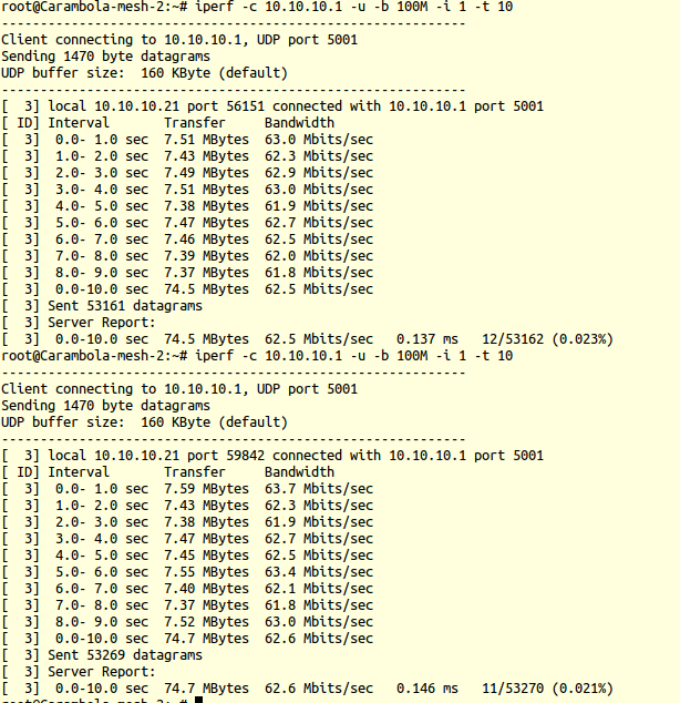
Throughput between these mesh enabled carambola-2 devices is measured using the iperf tool. You could build iperf as a package in OpenWRT and install it in these devices.
Devices are configured to form a mesh network with HT20 as follows:
iw mesh0 set channel 1 HT20
iw mesh0 mesh join mesh-test
A conducted cable setup with attenuators is made between these mesh enabled carambola-2 devices. Attenuators are added to not destroy the wireless card on the device.
These devices are placed inside an RF chamber, to measure throughput in a controlled environment.
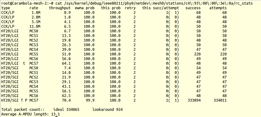
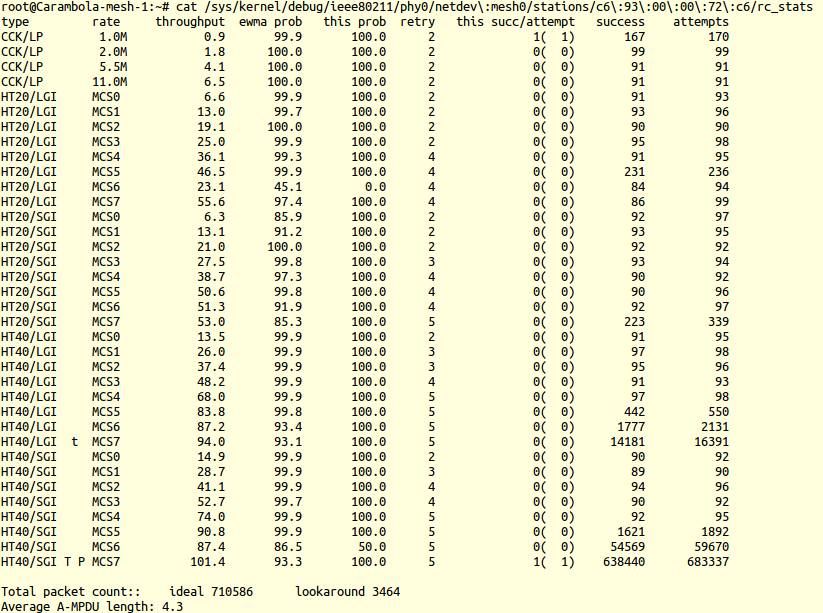
The following image shows the bitrate used by these devices during the iperf experiment. It is to be noted that carambola-2 devices have a 1x1 wireless card. The maximum data rate you could achieve on a 20MHz channel with a Short Gaurd interval is 72.2 MBit/s (MCS 07 SGI)

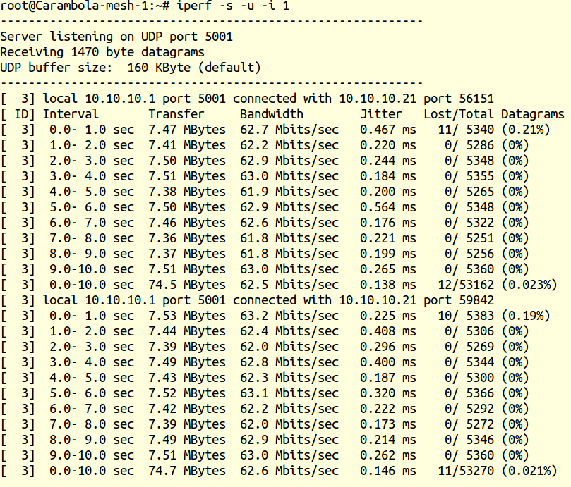
A throughput of 62.5 MBits/s is a good number you would like to see in a 20MHz channel width. Maximum bitrate that could be observed in a 20Mhz channel is 72.2 MBits/s (MCS 07 HT20 SGI)
#####Iperf client report:
The following statistics shows the different rates the device was trying to send its data after few iperf experiments
The above experiment is repeated with these mesh nodes operating on a 40MHz channel.
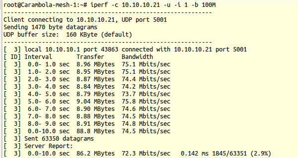
The following image shows the bitrate used by these devices during the iperf experiment. It is to be noted that carambola-2 devices have a 1x1:1 wireless card. The maximum data rate you could achieve on a 40MHz channel with a Short Gaurd interval is 150 MBit/s (MCS 07)

#####Iperf server report:

#####Iperf client report:
The following statistics shows the different rates the device was trying to send its data after few iperf experiments
These are the throughput numbers we have from a HT enabled mesh network on carambola-2 devices.
On a 20 MHz bandwidth: 62.5 MBits/s (Max bitrate: 72.2 MBits/s)
On a 40 MHz bandwidth: 72.3 MBits/s (Max bitrate: 150.0 MBits/s)
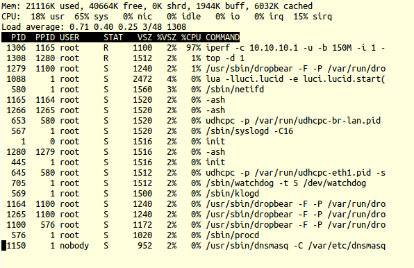
Reason behind a comparatively low performance of Carambola-2 mesh enabled devices on a HT40 network, comes from the Hardware limitation. Carambola-2 has a 400 MHz MIPS processor. Running a iperf experiment on a HT40 mesh network, it is observed that CPU is completely used (0% idle) whereas only a two third of the CPU is used when running a iperf on HT20 mesh network. Running a top on one of these carambola-2 mesh enabled devices during an iperf experiment running at background shows this
A secure mesh network could be established with these carambola2 devices with some additional packages build to the image. authsae will handle all authentication and mesh peering. Details on bringing up a secure mesh network is documented here.
Following authsae configuration is used to bring up a secure mesh network.
authsae:
{
 sae:
  {
    debug = 480;
    password = "thisisreallysecret";
    group = [19, 26, 21, 25, 20];
    blacklist = 5;
    thresh = 5;
    lifetime = 3600;
  };
 meshd:
  {
    meshid = "mesh-test";
    interface = "mesh0";
    band = "11g";
    channel = 1;
    htmode = "HT40+";
    mcast-rate = 12;
  };
};
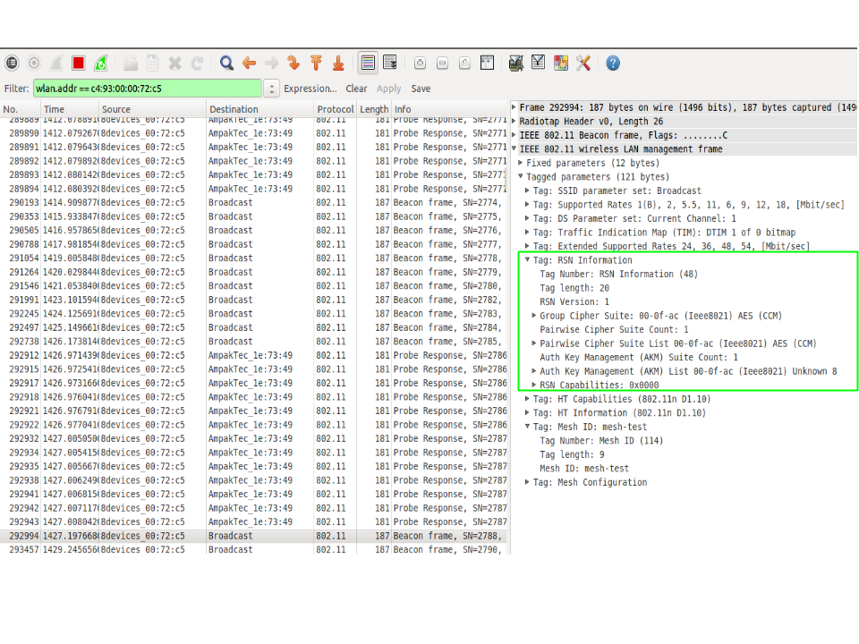
On analyzing an Over-The-Air (OTA) traffic captured near this mesh network shows Security related (RSN) Information Elements (IEs). The following images shows details of a mesh beacon frame from a carambola-2 device operating in a secured mesh network.
